Physical Installation (IP8M-1083EW-AI)
Basic Requirements
All installation and operation of this device should conform to your local electrical safety codes, fire prevention laws and some related regulations.
Please use the product according to the operating environment.
Please keep the original packing material well after opening the package; you can use original packing material to pack the camera and send it back for maintenance in case problems occur.
Installation Check
Make sure the installation site has enough space to hold the product and its mounting components.
Please make sure the ceiling or wall can sustain 8X weight of the camera and its mounting components.
Please make sure the wall is thick enough to install expansion bolts.
The installation height of the camera should be at a minimum 6m or 20ft from the ground when installing.
Speed Dome Installation
What’s Included?
Before installation, please check the accessories one by one. Please make sure all the components listed are included.
• Mounting Bracket
• 4 Expansion Mounting Bolts
• 3 Stainless Locking Screws
• Allen Wrench
• Security wrench (for removing the back plate of the camera)
• A Pair of Gloves (if needed)
• 2 carabiner security lock
• Speed Dome Camera
• 24.0V, 2.5A Switching adapter (for power without using PoE+)
• Ethernet Cable (for power with using PoE+)
• Roll of electrical tape
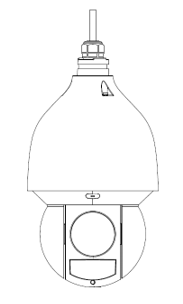
Open Device
Open the package and then remove the device.
MicroSD Card Installation
The camera can support up to a 256GB microSD card to store recordings and events. To install the microSD card, use the included security wrench to remove the rear cover of the camera. Locate the microSD card slot on the board and insert the card into the slot.

Secure the rear cover back onto the camera before physically installing the camera.
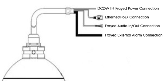
Wiring Overview
The camera will come attached with several dongle wire connections. These wires are used to power the device as well as provide the ability to connect an external microphone, speaker, or alarm. Please refer to the information provided below for more details.
|
Wire |
Purpose |
|
Power Connection |
Use these wires to splice the included DC24V, 2.5A switching adapter to camera. Please do not use this connection if you are powering your device using a PoE+ connection. |
|
Ethernet Connection |
Use this port to power your device and transmit data using PoE+. |
|
Audio In/Out Connection |
Use these wires to splice an external audio device, such as a microphone or speaker to the device. |
|
Alarm Connection |
Use these wires to splice an external alarm to the device. |
Please refer to the tags specified on the dongle wire connections for more details.
Camera Installation
Overview
Included with your camera you will notice a large wall mount bracket. This wall mount bracket will be used to secure your camera in place as well as to the mounting surface. Also included with your wall mount bracket will be three stainless steel locking screws, and mounting screws (expansion bolts). These will be used to secure the camera to the mount bracket as well as the mounting surface.
Note: Additionally, a 2 carabiners link will be included with the camera. This piece will be used to provide additional support to the camera after installation.

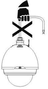
When installing the camera, do not pull the cable to lift the camera when moving the device as it may cause internal damage to the camera.
Installation Steps
Before installation, please ensure the installation surface is close to a network and power connection and can support up to 8x the weight of the camera. Please refer to the steps below to being installation.
Step 1: Using the mounting holes on the wall-mounted bracket bottom as a template (align the bottom of the bracket with the circular hole on the wall) and using a marker or pen draw the installation holes on the mounting surface.
Step 2: Drill the holes. Remove the nut and 2 washers from the expansion bolt and insert the sleeve of the expansion bolt and the bolt into the drilled holes. Do not lose the nuts and washers.
Step 3: Take the dongle wire connections and run them through the arm of the wall-mounted bracket. Align the top of the camera with the arm of the wall-mounted bracket and place the bracket flush with the camera. Connect any wires necessary to its applicable dongle wire connection.
Using the Switching Adapter to Power the Camera
The camera can be powered using a PoE+ connection which will provided data and power to your camera, however, if PoE+ is not an option the camera can be powered using the included DC24V, 2.5A switching adapter. If you are using this method to power your camera, please ensure that a wall outlet is close by. DO NOT APPLY POWER TO THE ADAPTER UNTIL THE CONNECTION HAS BEEN SECURED.
It is recommended to use gloves during this process. To begin, splice the ground wire (black) to the marked ground wire of the switching adapter and splice the DC24V (+) (red) wire to the power in wire of the switching adapter. Use electrical tape to ensure the connection is secured. Then, connect the power cable to the switching adapter and connect it to a wall outlet. The device will begin to boot.
Note: Ensure that an Ethernet cable is attached to the camera and your network before installing the camera and bracket to the mounting surface.
Step 4: Insert an included rubber washer into the back of the wall-mounted bracket and secure the camera to the wall-mounted bracket using the 3 stainless steel locking screws. Insert the screws into the respective holes on the arm of the wall-mounted bracket and use the included allen wrench to tighten the screws to secure the camera to the arm.
Step 5: Feed any wiring back into the installation surface and place the installation holes on the bottom of the mounting bracket into the 4 expansion bolts located on the mounting surface. Insert the split washer and solid washer onto the expansion bolt and hand tighten the nut to the bolt. Repeat the process for the other 3 expansion bolts. Then, using a socket wrench or similar tool, secure the nuts to the expansion bolts. The camera is now successfully installed.
Comments
Please sign in to leave a comment.