Physical Installation Guide (Turret Camera)
To install the camera on a ceiling or wall, please reference the below diagram as well as the steps:
Note: Prior to installation, please ensure that the installation environment can support at least 3x the weight of the camera and bracket.
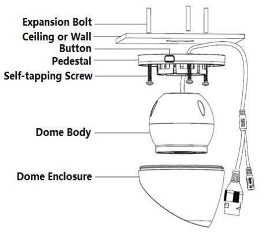
Figure2-1 (a)
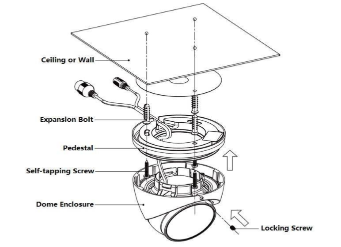
Figure 2-2 (b)
Note: Due to specific hardware limitations within your camera it is important to note that these devices will not be able to automatically pan/tilt or pivot in either the app or via the web UI on a computer. For this reason, it is important to make sure to mount the cameras properly and position them as efficiently as you can to the areas you wish to monitor. All positioning actions to the camera will have to be performed manually.
To install the camera onto a wall, follow the steps below:
1. Place the included mounting template to the mounting surface.
2. Drill bottom holes according to the installation position map and then insert three expansion bolts into the bottom holes. Secure these three bolts firmly.
Note: If you are running the cables through a wall, use a 1" paddle bit to run the wires through the opening.
3. Disassemble the device For the device shown in Figure2-1 (a), the steps of disassembling the device are as follows: Step 1 Press the button on the pedestal to make it expand. Step 2 Press the dome enclosure down the cable exit to separate the pedestal and the dome enclosure and disassemble the device.
For the device shown in Figure 2-2 (b), loosen the locking screw, pull the enclosure downward, and then disassemble the device.
4. Select run the wire through bottom or side and insert multi-function cable into exit hole on installation surface.
Bottom wiring: select to lead out the cable through ceiling or wall, which can protect the cable effectively.
Side wiring: Select to lead out the cable through side exit and add metal conduit, etc, which can prevent the cable from being destroyed.

5. Adjust pedestal position, aim at bottom hole. Take out three ST4.2 self-tapping screws in accessories bag. Insert them into the plastic expansion bolt bottom hole and fix the pedestal on installation surface. 6. Waterproof connector installation for network port; see Figure 2-6 for more details.
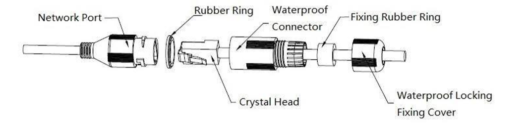
Figure 2-6
1. Keep the convex groove outward and install the rubber ring into the network port, keep the smaller hole of the rubber ring outward and install the fixing rubber ring into the main body of the waterproof connector.
2. Pull the network cable without crystal head through main body of waterproof connector, fixing rubber ring and waterproof locking cover, make the crystal head of network cable, and then insert it into the network cable.
3. Put the main body of waterproof connector on the network port and rotate it clockwise to lock the network port and waterproof connector firmly. Put the waterproof locking cover on the main body of waterproof connector and rotate it clockwise to lock the waterproof connector and waterproof locking cover firmly.
Comments
Please sign in to leave a comment.